- Academy
Application of Changeover switch function in EOD-3902 and OED-3904
EOD-3902 is a dual SDI to optical converter for 3G/HD/SD-SDI electrical signals to optical signals, and OED-3904 is a dual converter of optical signals to 3G/HD/SD-SDI electrical signals. Both devices feature “Change Over” and “Recover” capabilities. When the “Change Over” is enabled, if one of the input signals is lost, its corresponding outputs are fed by the other input. In this case, when the lost input is retrieved, the signal won’t be connected to its outputs. However, if the “Recover” mode is enabled, the retrieved signal will be automatically switched back to its outputs again. All adjustments and controls can be applied directly by onboard DIP switches and web interface remote control.
Redundant Sources and Protection Options
For situations where we have two redundant sources of content in the optical communication link, for example, a studio that has two cameras to send video to the destination, two types of protection can be created for the communication link by SDI to optical converter like these products.
- Path protection
- Path and system protection
In the following, for short we will name EOD-3902 as EOD and OED-3904 as OED.
Path protection setup
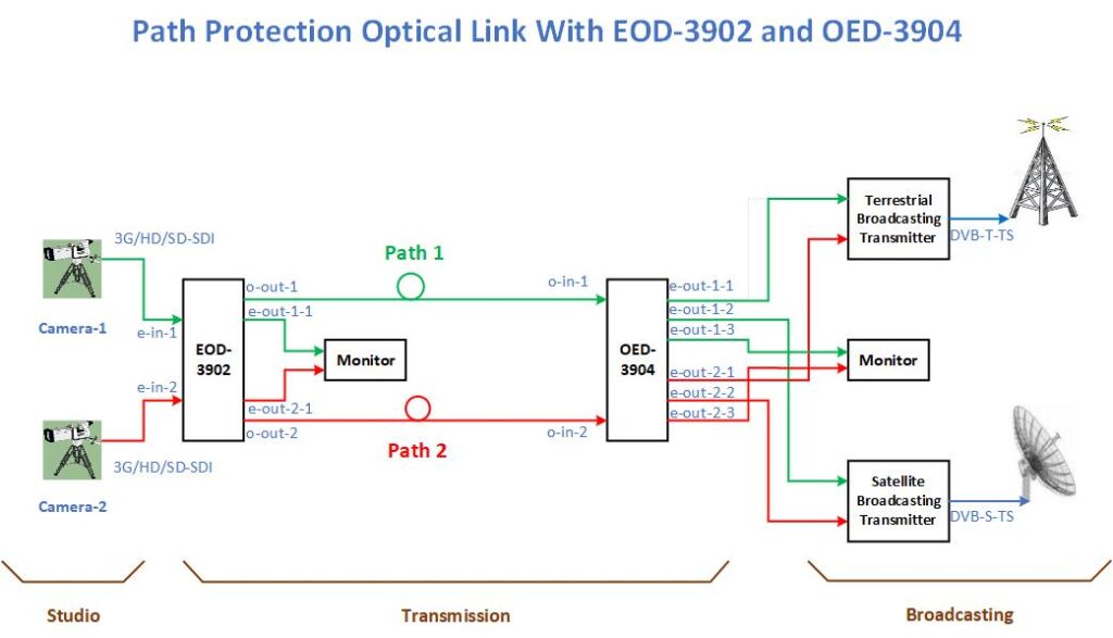
If you have an EOD module, an OED module, and an optical fiber in two communication paths, according to the figure and the following steps, the signal of the studio cameras can be sent to the two destinations of the terrestrial broadcasting station and the satellite broadcasting station with path protection.
- Set EOD in Changeover or Recover mode.
- Connect the output of the first camera to the first input of the converter and the output of the second camera to the second input.
- Connect the first optical output of the EOD to the optical fiber of the first path and the second optical output to the optical fiber of the second path.
- Set OED in Changeover or Recover mode.
- Connect the optical fiber of the first path to the first optical input of the converter and the optical fiber of the second path to the second optical input.
- Connect the first output of the first and second inputs of OED (e-out-1-1, e-out-2-1) to the inputs of the terrestrial broadcasting system.
- Connect the second output of the first and second inputs (e-out-1-2, e-out-2-2) to the inputs of the satellite broadcasting system.
- Additional electrical outputs can be used to monitor input signals.
In such a situation, in the event of a failure of one of the cameras and the cut of the optical fiber in one of the communication paths simultaneously, with the switching function in the modules, the signal of the other studio camera will reach both inputs of the terrestrial and satellite broadcast systems.
Path and system protection
If you have two EOD modules, two OED modules, and two optical fibers in each of the two communication paths, according to the figure and the following steps, path and system protection can be established for the communication between the studio and the terrestrial broadcasting station and the satellite broadcasting station.
OED products handle switching in the satellite broadcasting path, from the studio to the satellite.
- Set the first and second EODs in Changeover or Recover mode.
- If the cameras have two outputs, give the first output of the first camera to the first input of the first converter and the second output of the first camera to the first input of the second.
- Connect the first output of the second camera to the second input of the first EOD and the second output of the second camera to the second input of the second EOD.
(If the cameras have only one output, use two video signal distributors to create two outputs from the cameras and connect them to the converters.) - Connect the first optical outputs of the first and second converters to the first and second optical fibers of the first path.
- Connect the second optical outputs to the first and second optical fibers of the second path.
- Set the first and second OEDs in Changeover or Recover mode.
- Connect the first and second fibers of the first path to the first optical inputs of the first and second OED.
- Connect the first and second fibers of the second path to the second optical inputs of the first and second converters.
- Connect the first outputs from the first input of the first and second OEDs to the terrestrial broadcasting input system A and the second outputs from the first input of the first and second OEDs to the terrestrial broadcasting input system B.
[(e1-out-1-1 and e2-out-1-1 to AT), (e1-out-1-2 and e2-out-1-2 to BT)] - Connect the first outputs from the second input of the first and second OEDs to the satellite broadcasting input system A and the second outputs from the second input of the first and second OEDs to the satellite broadcasting input system B.
[(e1-out-2-1 and e2-out-2-1 to AS), (e1-out-2-2 and e2-out-2-2 to BS)] - Additional electrical outputs can be used to monitor input signals.
If each of the terrestrial and satellite broadcast systems only have one system to receive inputs, connect the output e1-out-1-1 to the first input of the terrestrial broadcasting system and the output e2-out-1-2 to the second input. Also, connect the output e1-out-2-1 to the first input of the satellite broadcasting system and the e2-out-2-2 output to the second input.
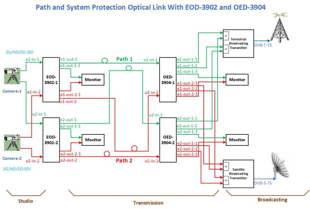
In the state of path and system protection, in case of failure of one of the cameras and failure of the corresponding converter (for example, EOD-1 and OED-1) and cut of optical fibers in one of the communication paths simultaneously, with the switching function in the other modules, the signal from the studio’s other camera will reach the inputs of terrestrial and satellite broadcasting systems.


