
- Academy
- Article
Optical Communication (Part 2)
In this technical blog post and the 2 parts later, we cover almost everything about the optical communication platform which is a reliable and robust means to send and receive most of data, information, and signal.
Losses and their types in optical fibers
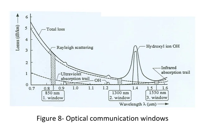
Light waves lose some of their energy when passing through fiber optics. Fiber loss is considered an important parameter that can be caused by the production process, fiber constituent materials, bends, and tension. Impurities in fiber increase losses. The amount of loss in the fiber changes in different wavelengths. For example, losses are less in wavelengths of 1550 and 1300 nm. In fiber optic communication, according to Figure 8, these two wavelengths are known as the second and third windows of optical communication, respectively.
According to the definition, losses are expressed in terms of decibels per kilometer (dB/Km) and are calculated with the following equation.
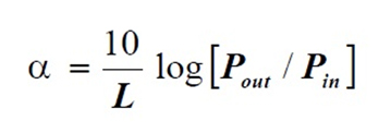
where Pout is the output power of the light from the fiber, Pin is the input power of the light to the fiber and L is the length of the fiber.
In general, losses in optical fibers are divided into two categories: inherent and acquired.
Inherent losses
Inherent losses in the fiber are absorption type. It means that the light energy that spreads inside the fiber is absorbed by the materials that make it up and turns into heat. Intrinsic losses are of two types, which are called ultraviolet and infrared losses. Fiber-forming materials naturally absorb some of the light energy depending on the frequency in the range of ultraviolet and infrared spectrum and cause losses. In wavelengths between 1.2 and 1.3 microns, there are almost no losses due to infrared absorption, and the amount of losses due to ultraviolet absorption in this range is negligible.
Acquired losses
Acquired losses occur due to the presence of impurities in the fiber. Impurities are of two types, metallic and non-metallic.
Metal type impurity
If metal ions of iron and chromium enter the core of the fiber, they will cause losses in the fiber and their amount should not be more than 1ppb. In addition to increasing total losses, the presence of these types of impurities decreases fiber strength and increases the percentage of fiber breakage in mechanical tests.
Non-metallic impurity
The presence of OH non-metallic ion in the glass network forming the fiber causes losses in fiber optics because the oscillation frequency of this molecule is equal to the frequency of light. The amount of OH ion impurity in the fiber should not exceed more than 1ppm. The loss caused by OH ion occurs at the wavelength of 1380nm, and in addition to the main oscillation, its other harmonic at 1250nm also increases the total loss in the fiber. OH, ion enters its glass network during fiber production.
Rayleigh scattering losses
This type of loss occurs due to the phenomenon of ray scattering in the fiber. Rayleigh scattering is caused by the addition of germanium dioxide in the core of the fiber. The presence of germanium dioxide in the core of the fiber causes inhomogeneity in the refractive index of the core region, which is comparable to the wavelength of light, which in turn causes the scattering of the light emitted in the fiber, and as a result, losses increase. Rayleigh scattering losses occur in shorter wavelengths and are proportional to the inverse of the fourth power of the wavelength, so it decreases with increasing wavelength.
waveguide losses
Waveguide losses in the fiber occur due to the unevenness of the common surface of the core and cladding. The cause of this type of loss should be found in the construction process, which can be both during the construction of the pre-structure and in the tensioning process. To avoid or minimize waveguide losses, the different stages of the production process must be precisely controlled.
Micro-bending losses
These losses occur due to the bending of the fibers, which are created in the manufacturing process or the cabling stage. A stage of fiber manufacturing in which micro-bends occur is the fiber stretching stage, which occurs due to improper application of coating materials. At the time of cabling, great care is needed to prevent micro-bends in the fiber.
Total losses in optical fibers
The set of inherent and acquired losses in a fiber determines the total loss of the fiber, part of which is created during production and the other part during cabling and its use. The total loss can be expressed by the following relationship:
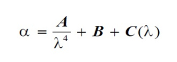
where A is the Rayleigh scattering coefficient, B is a constant coefficient and C is a variable coefficient and a function of wavelength.
Dispersion in optical fiber
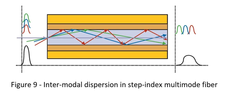
Dispersion in optical fibers is a well-known phenomenon that causes the propagation of light pulses in it. In general, the dispersion phenomenon is divided into two types of dispersion, inter-modal and extra-modal, or chromatic dispersion, according to the type of fiber. In multi-mode fibers, there are both types of inter-modal and chromatic dispersion, but in single-mode fibers, the dispersion is only chromatic. According to Figure 9, inter-modal dispersion in multi-mode optical fiber is caused by the optical propagation modes not reaching the end of the fiber at the same time, and this phenomenon causes the output pulse to widen at the output of the fiber. Chromatic dispersion in single-mode fibers is divided into three types of material dispersion, waveguide and profile dispersion.
Material dispersion
The value of the refractive index of glass changes according to the wavelength of light. In mathematical terms, the second derivative is called the refractive index of the fiber in terms of the material’s dispersion wavelength, which is expressed in the form of the following equation :
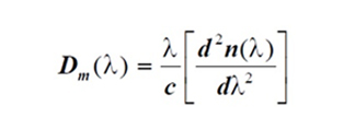
where n, c, and λ are the fiber’s refractive index, the speed of light in vacuum, and the wavelength of light, respectively.
waveguide dispersion
How the main mode is distributed in the core and cladding when light is emitted into the fiber depends on the wavelength of the light. The longer the wavelength, the more amount of the main mode is emitted in the cladding. Because the cladding refractive index is less than the core refractive index, the speed of the main mode in the cladding will be higher than its speed in the core. Now, if a slight change in the value of the wavelength of the light during propagation occurs, waveguide dispersion Dw(λ) is created. Usually, in single-mode fibers, there is waveguide dispersion and it is a function of the wavelength, which is expressed by the following equation.
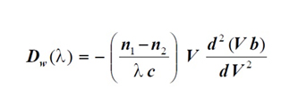
where V is the normalized frequency, b is the normalized propagation constant, n1 and n2 are the refractive index of the core and cladding respectively, c is the speed of light and λ is the wavelength of light in vacuum.
Dispersion profile
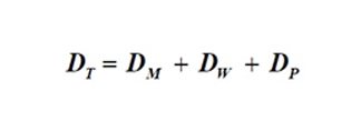
In single-mode fibers, the dominant dispersions are material dispersion and waveguide dispersion, but the dispersion caused by a disorder in composite profiles (such as double-cladding and four-cladding fibers) should not be ignored inaccurate calculations, although the amount of dispersion profile is small and less than 0.5 ps/nm.km. Chromatic dispersion DT consists of the sum of material dispersion DM, waveguide dispersion DW, and profile dispersion DP.
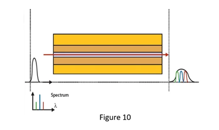
In multimode fibers, intermodal dispersion is the dominant dispersion, which is caused by the simultaneous propagation of different modes in multimode fibers, which causes the optical pulses to be too wide, so that, this type of fiber is undesirable for long-distance telecommunications. The dispersion value of ordinary single-mode fibers is less than 3 ps/nm.km at the wavelength of 1300 nm, and 15 ps/nm.km at the wavelength of 1550 nm. It should be noted that the nm dimension in the dispersion measurement unit is related to the spectrum width of the light source. In Figure 10 you see the schematic of chromatic dispersion in the emission of several wavelengths in a single-mode fiber, which caused the uneven arrival of the wavelengths at the end of the fiber and the broadening of the pulse.
Read also :
Optical Communication (Part 3)
Polarization Mode Dispersion (PMD)
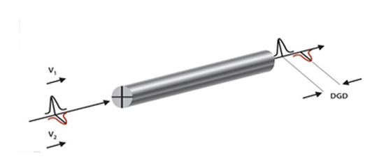
Polarization mode dispersion is one of the phenomena that occurs when sending a bit rate of more than 2.5 Gb/s in an optical link, and like chromatic dispersion, it causes the spread of optical pulses in the fiber during message transmission and increases with the square of the network length. The dimension of PMD quantity is (ps/Ökm). The phenomenon of PMD in optical fibers is caused by the deviation of the cross-sectional area of the fiber from its circular state, which in turn can be caused by factors such as transverse stress in the cross-sectional area of the fiber that occurs during production or use. This causes two perpendicular polarization modes of the LP mode of the fiber to propagate at different speeds along the length of the fiber and as a result, reach the end of the fiber with a time delay and result in the broadening of the received pulse. The standard value of PMD in telecommunication fibers is less than O.2 ps/Ökm. In the following figure (11) you can see PMD, as a result of which two polarization modes reach the end of the fiber with a time difference and lead to the broadening of the resultant pulse.
Cutoff wavelength in optical fiber
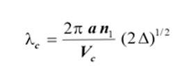
The cut-off wavelength of a fiber is the minimum wavelength that emits any wavelength more than that in a single mode. During propagation in a single-mode fiber, if the wavelength of the light source is less than the cut-off wavelength, the sub-modes are also propagated along with the main mode, in this case, the single-mode fiber acts like a multi-mode fiber. The cutoff wavelength of each fiber is determined at the time of manufacture and is a parameter that strongly depends on other manufacturing parameters. The cutoff wavelength of single-mode fibers is determined by the following equation:
Mode field diameter (MFD)
where Vc is the normalized cutoff frequency, ‘a’ is the core radius, n1 is the refractive index of the core and ∆ is the difference of the relative refractive index.
The diameter of the mode field is called the width of the mode light intensity distribution when its value is reached 1∕ⅇ^2 times of maximum intensity. The amplitude of light intensity on the core axis, i.e. in the radius r = 0 has a maximum value. The value of MFD increases with increasing wavelength. In single-mode fibers, the amount of MFD is approximately equal to the diameter of the core, that is, approximately 10 micrometers.
By knowing the cutoff wavelength and fiber optic radius, the MFD value of the fiber can be calculated for a defined wavelength with the following equation:
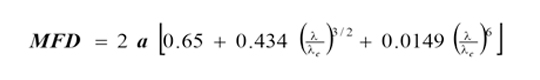
where ‘a’ is the fiber radius, λ is the working wavelength, and λc is the cutoff wavelength.
Bandwidth in optical fibers
In fiber optic telecommunication systems, bandwidth is a parameter that determines the capacity of sending messages, or in other words, plays an important role in determining the number of telecommunication channels. In fiber optic telecommunication, the two parameters of bandwidth and dispersion are interdependent, so that the bandwidth decreases with the increase of dispersion. In each frequency, the ratio of output power to input power is called the transfer function. Bandwidth (B) refers to the frequency in which the relative amplitude of optical power has reached half of its value compared to zero frequency. The transfer function or the relative amplitude of power is expressed as follows:
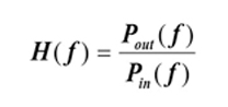
where Pout and Pin are the output power and the input power of the light to the fiber, respectively.
In a digital optical system, the bit rate (BT) of pulses propagated in fiber optics is at most equal to the inverse of the pulse width (2τ):
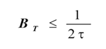
Which is the value of BT for the case where there is no overlapping of pulses.

- Article
- Academy
Modern Playout Infrastructure in Broadcast Workflows
“Modern playout in broadcast workflows” refers to the contemporary methods, technologies, and processes used to manage and deliver live or pre-recorded video content to viewers through advanced playout facilities and…

- Article
Engineering Broadcast Delay Systems for Live Radio: Technical Standards and Smart Integration
In the field of live radio broadcasting, audio delay and radio broadcast delay systems play a critical role in content control, quality assurance, and safety. These systems are especially important…

- Article
Live Sports Production Workflow Explained: Tools & Tips
Live sports broadcasting is one of the most demanding and fast-paced types of production in the media industry. It requires careful planning, advanced technology, and a skilled team to pull…

- Article
What Really Powers a Successful Live Broadcast production? Key Components Uncovered
A successful live broadcast hinges on a combination of advanced technical infrastructure, skilled human resources, thorough planning, and reliable equipment. This research delves into the vital elements that underpin successful…

- Article
Building a Future-Proof News Broadcast Studio: Key Components and Best Practices
The rapid evolution of technology and changing viewer expectations require news broadcast studios to be adaptable, scalable, and resilient. This research explores the essential components and best practices for designing…
- Article
Why Color Bars Remain Essential in Modern Digital Broadcast System
Color bars remain essential in modern digital broadcast systems because they serve as a universal reference standard for image quality, calibration, and troubleshooting. They help ensure consistent color reproduction, luminance,…

- Article
TV Headend Equipment Explained: Applications & Key Benefits
The digital headend in TV broadcasting serves as the central hub for aggregating, processing, and distributing television signals to subscribers. Its evolution from analog to digital systems has significantly enhanced…
- Article
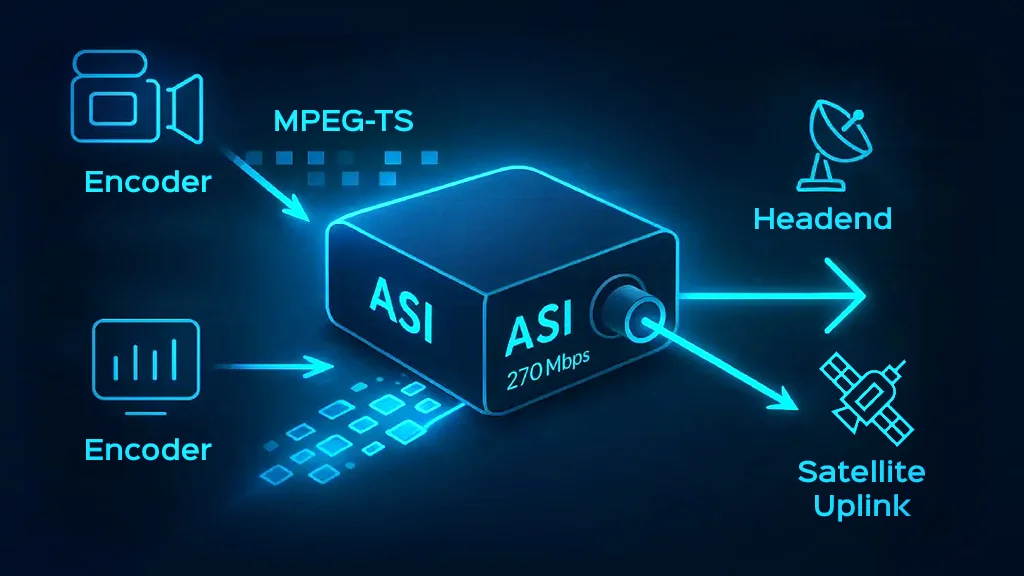
ASI in Broadcast Transport Streams: The Backbone of Digital TV Signal Distribution
Asynchronous Serial Interface (ASI) signals are pivotal in distributing digital television signals, especially within the broadcast infrastructure. This article examines the critical role of ASI in broadcast transport streams, highlighting its…

- Academy
A Detailed Overview of TV Transmission Sites
In an era where broadcast media remains a dominant force in information dissemination, understanding the essential equipment for TV transmission sites is crucial. This guide provides a comprehensive overview of…
- Article
- Academy
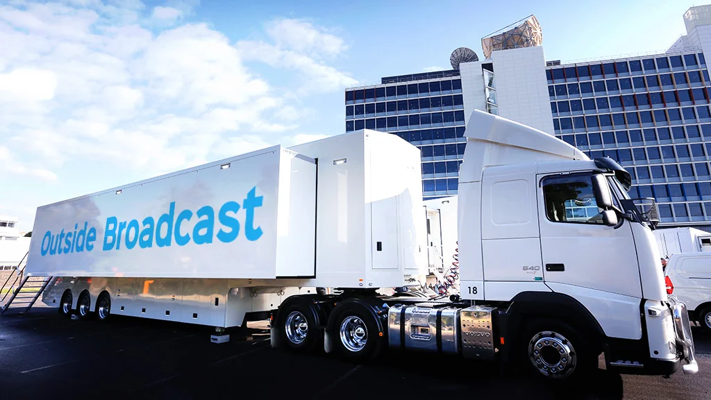
Taking Your Broadcast Outside: Essential Considerations and Pro Tips
Outside broadcasting (OB) encompasses various challenges and opportunities that media professionals face when delivering live content in diverse outdoor environments. This blog explores the essential considerations necessary for successful OB,…